
Revision Questions
1. Describe, with the aid of diagrams, experiments to investigate the magnetic field patterns around each of the following current-carrying conductors:
- a straight wire
- b solenoid
Your diagrams should clearly indicate the direction of the current and the field.
2. Describe, with the aid of a diagram, one commercial application of an electromagnet.
3. Describe an experiment which indicates that there is a force on a current-carrying conductor placed in a magnetic field.
4. Magnetic Thrust and Motors
Figure 32.19 shows electrical currents flowing through magnetic fields. Determine the direction of the thrust on the conductors in each case.
5. Sketch the magnetic field diagram for Figure 32.19(a).
6. With the aid of a diagram, explain the functioning of a simple dc motor.
7. Describe how an induced current can be produced in a metal rod.
8. Electromagnetic Induction
Redraw Figure 32.20, showing the current direction in the solenoid and the magnetic polarity at its ends, for each of the following cases:
- a The N pole of the magnet is pushed into the coil.
- b The N pole of the magnet is left at rest in the coil.
- c The N pole of the magnet is withdrawn from the coil.
Figure 32.20
9. State THREE ways by which the current produced in question 8 may be increased.
10. Sketch a diagram of a simple ac generator.
11. With the aid of a diagram, explain how a transformer can transfer electrical energy from its primary coil to its secondary coil.
12. State TWO advantages of using ac for the long-distance transmission of electricity.
13. An ideal transformer has \( 4000 \) turns on its primary coil and \( 200 \) turns on its secondary coil. The primary coil is connected to a \( 120 \text{ V ac} \) mains supply and the secondary to a \( 4.0 \, \Omega \) device. Draw a circuit diagram of the arrangement, and determine:
- a the voltage across the \( 4.0 \, \Omega \) device
- b the current through the secondary coil (and through the device)
- c the current in the primary coil
- d the power input and the power output.
Exam-Style Questions
1. Structured Questions
a) Complete Table 1 to compare the properties of the zinc-carbon cell and the lead-acid accumulator.
(4 marks)| Property | Zinc-carbon cell | Lead-acid accumulator |
|---|---|---|
| Electrolyte | ||
| Rechargeability | ||
| Terminal voltage | ||
| Maximum current | \( > 400 \text{ A} \) | |
| Internal resistance | \( 0.01 \, \Omega \) |
b) i) Distinguish between the directions of conventional current and electron flow. (2 marks)
ii) State a type of conductor in which both positive and negative charges translate freely. (1 mark)
c) A charge of \( 480 \, \mu\text{C} \) flows through a resistor of resistance \( 500 \, \Omega \) in a period of \( 12 \text{ ms} \). Determine:
- i) the current (2 marks)
- ii) the potential difference across the resistor (2 marks)
- iii) the number of electrons which flow (the charge on each electron is \( -1.6 \times 10^{-19} \text{ C} \)) (2 marks)
- iv) the electrical energy transformed. (2 marks)
2. Fields and Magnetic Force
a) Figure 1 shows two oppositely charged particles and Figure 2 shows a current flowing in a wire perpendicularly into the plane of the paper between two magnetic poles.
i) Sketch the electric field lines between and around the particles of Figure 1 and the magnetic field lines associated with the current and magnetic poles of Figure 2. (6 marks)
ii) By means of an arrow labelled \( F \), show the direction of the force on the current-carrying conductor in Figure 2. (1 mark)
3. Circuit Resistance and Power
b) i) Determine the combined resistance between X and Y of Figure 3(a) and between P and Q of Figure 3(b). (4 marks)
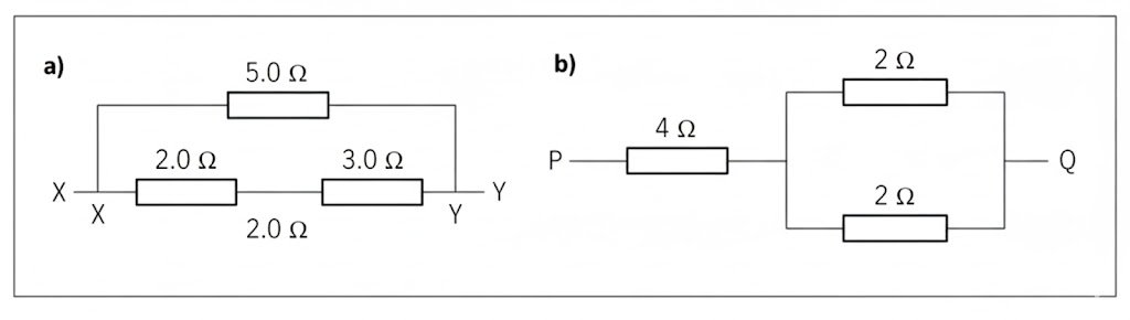
A current of \( 1 \text{ A} \) flows in the \( 4 \, \Omega \) resistor of Figure 3(b). Determine:
- ii) the potential difference across the parallel section of the circuit (2 marks)
- iii) the total power used by the three resistors. (2 marks)
Extended Response Questions
3. a) Sketch graphs of current against voltage for each of the following components when the potential difference is varied across them. Both graphs should have positive and negative axes.
- i) Filament lamp (3 marks)
- ii) Semiconductor diode (3 marks)
A graph of current against potential difference for a particular component is a straight line and passes through the origin.
iii) What can you deduce about the resistance of the component? (1 mark)
b) The variable resistor (rheostat) shown in Figure 4 has a maximum resistance of \( 10 \, \Omega \).
Figure 4
The rheostat is initially set to \( 0 \, \Omega \). Determine:
- i) the current in the circuit. (2 marks)
The rheostat is adjusted to have its maximum resistance. Determine:
- ii) the new current (2 marks)
- iii) the potential difference across resistor A (2 marks)
- iv) the power used by A. (2 marks)
Total 15 marks
4. a) i) Explain how a transformer can alter the value of an alternating voltage. (3 marks)
ii) State THREE advantages of using ac for transferring electrical energy. (3 marks)
b) i) Indicate, by means of arrows, the directions of the current induced in the metal rod and in the coil of Figure 5. (3 marks)
ii) Mark the induced north pole of the coil with the letter N. (1 mark)
iii) Indicate the polarity of the rod by marking + at the correct end. (1 mark)
c) An ideal transformer has 6000 turns and 1000 turns on its primary and secondary coils respectively. It is used to operate a \( 100 \text{ W} \), \( 20 \text{ V} \) device. Determine:
i) the input voltage (2 marks)
ii) the current in the secondary coil. (2 marks)
Total 15 marks